
A shiny surface
defeats a fixed rule.
AI inspection for metal and machined parts — surface defects on specular faces, and dimensional checks recorded as values rather than pass or fail.
Test it on your productThe Hard Case
On a reflective surface, the image changes even when the part does not.
Specular metal is the classic hard case in industrial vision. The same part, presented twice with a fractional difference in angle, produces two different images — and a rule-based system reads that difference as a defect, or misses a real one hidden in a highlight.
This is why so many metal inspection projects stall. The instinct is to tighten the rule, which increases false rejects, or to loosen it, which lets defects through. Neither converges, because the variability is in the imaging rather than in the part.
A model trained on your own parts learns what your surface actually looks like across the presentations it really has, including the reflections. That is a different approach from measuring against a threshold, and it is the reason it holds where rules do not.
Deep learning is the accepted answer where rules fail.
Learned models are widely used specifically for glossy and specular surfaces, where classical rule-based methods break down. The method is not mandated anywhere — it is chosen because it works.
Measured values, not verdicts.
Dimensional checks are recorded as actual values for every part, so tool wear appears as a trend well before parts start failing.
What it checks
The checks an metal line
actually needs.
Is the face acceptable?
Surface defects
Scratches, scoring, porosity, pitting, inclusions and handling damage on machined and formed surfaces.
Is it within tolerance?
Dimensional check
Key dimensions recorded as values for every part, making tool wear visible as drift rather than as scrap.
Is the finish to specification?
Tool marks & finish
Machining marks, chatter and finish consistency across the face.
Are the edges clean?
Burr & edge
Burr presence and edge condition after machining, stamping or cutting.
Are all features there?
Hole & feature presence
Presence, position and count of holes, threads, slots and machined features.
Is the coating sound?
Coating & plating
Coverage, thickness appearance, blistering and bare patches on coated and plated parts.
Does the weld look sound?
Weld appearance
Visual weld condition, spatter, seam position and undercut on visible joints.
Is the part clean?
Foreign material
Swarf, coolant residue and debris on faces and in cavities before the next operation.
Is this the right part?
Part identification
Confirms the part running matches the job, catching mixed parts before they move downstream.
Built for the environment
Coolant, swarf, heat and
mixed geometry.
Electronics is less mechanically hostile than metalworking but far less forgiving on imaging. These are the conditions the hardware is specified against.
ENVIRONMENT
Built for stability. Designed for real-world conditions.
- Coolant and oil mistSealed housings with air purge where required
- SwarfMounting and shielding positioned out of the chip path
- VibrationIsolated mounting away from machine and conveyor movement
- HeatPlacement specified for hot parts and hot processes
- Mixed geometryFixturing and presentation designed for the part family, not a single part
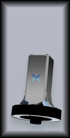
IMAGING
Clearer vision. Smarter inspection.
- Specular surfacesDome, diffuse and multi-angle lighting to control reflection
- Fine surface defectsResolution matched to the smallest defect at working distance
- Geometry and depth3D sensing where form, height or flatness matters
- DimensionsTelecentric optics where measurement accuracy is the objective
- Dark and coated metalIllumination selected for low-contrast surfaces
- Multiple facesSeveral inspection points or reorientation for all-round coverage
On lighting. On specular metal, lighting is the entire problem. A dome or diffuse arrangement removes the highlights that a directional light creates, and the geometry is specified per part family and validated on real parts across the presentations they arrive in.
Where the record matters
Your customer asks for
numbers, not assurances.
Metal and machined parts are usually sold against a drawing, and the evidence expected is measured rather than asserted.
Per-part measured values
Dimensional results are recorded as values for every part inspected, which is the form an inspection report or a customer query actually requires.
Drift before scrap
Continuous measurement shows a tool approaching its limit as a trend, which is actionable, rather than as a batch of rejects, which is not.
Traceable records
Every part inspected is logged with its result and an image reference, retained on your own infrastructure for as long as your customer agreement requires.
The platform
Same three components,
tuned to your product.



Standards & codes
The standards your welds
and surfaces are judged against.
The published criteria your customers, auditors and quality team already reference. We train models against your interpretation of these standards — we do not certify conformance to them, and an inspection result is not a conformity assessment.
ISO 6520-1
What it covers
Classification of geometric imperfections in metallic materials, for fusion welding. Provides the designation and numbering system used to name each imperfection type.
Where it applies
Naming the defect your drawing or inspection report refers to
ISO 5817
What it covers
Welding — Fusion-welded joints in steel, nickel, titanium and their alloys (beam welding excluded) — Quality levels for imperfections. Defines Levels B, C and D for material 0.5 mm and above, with B the most demanding.
Where it applies
Visual weld appearance against the level your customer specifies
Metal & machining questions
What machining teams ask first.
This is the case the approach is best suited to. Reflective surfaces defeat fixed rules because the image changes with presentation, which is exactly why a model trained on your own parts across their real presentations holds where a threshold does not. Lighting geometry does the other half of the work.
- Can it measure, or only detect?
- Does it replace our CMM?
- Can it survive coolant and swarf?
- We machine a wide family of parts. Does each need its own setup?
Still deciding
The one question this page can't answer:
does it work on your defect?
Start here
Send us your images
Share examples of the defect you care about. We train a model on your product and come back with a straight answer — including if it's no.
Start a feasibility checkOr ask directly
Talk to an engineer
Thirty minutes with someone who builds this. Bring your line speed, your defects and your integration constraints.
Get a demo